Troubleshooting PCB Sispasta para soldar con cautinolder paste indiumgnal Integrity Issues with Impedance Testinglow temp solder pastepasta made in italy sold in usasmd solder paste
Troubleshooting PCB Signal Integrity Issues with Impedance Testing
Author : Colby September 15,solder paste indium 2025Table of Contents
If you're dealing with PCB signal integrity problems, impedance testing could be the key to identifying and resolving issues like signal reflections, crosstalk, or data corruption. In this comprehensive guide, we'll walk you through the essentials of troubleshooting these issues using techniques such as TDR testing for PCBand VNA testing for PCB. You'll learn how to detect and fix PCB impedance mismatchproblems with practical steps and tools, ensuring your high-speed designs perform reliably.
Why Signal Integrity Matters in PCB Design
In modern electronics, where data rates often exceed several gigabits per second, maintaining signal integrity is critical. Signal integrity refers to the quality of an electrical signal as it travels through a printed circuit board (PCB). Poor signal integrity can lead to errors, delays, or complete system failures, especially in high-speed applications like telecommunications, computing, and automotive systems.
Common PCB signal integrity problemsinclude signal reflections, crosstalk, and electromagnetic interference (EMI). These issues often stem from impedance mismatches, improper trace routing, or inadequate grounding. For instance, a mismatch in impedance can cause up to 50% of the signal energy to reflect back, leading to distorted waveforms and data loss. Addressing these challenges starts with understanding and testing for impedance issues, which we'll explore in detail.
What Is Impedance and Why Does It Cause Problems?
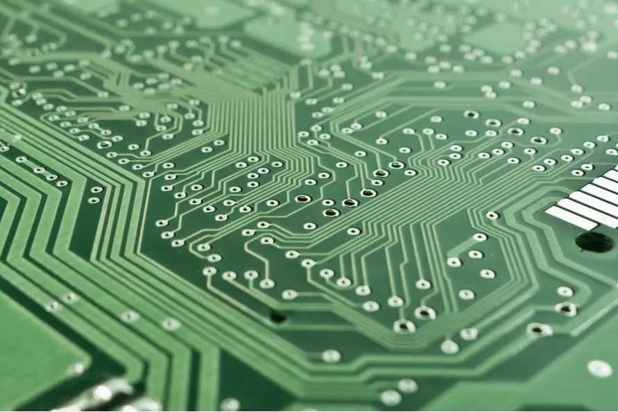
Impedance is the measure of opposition to the flow of an alternating current (AC) signal in a circuit. In PCBs, it is determined by factors like trace width, dielectric material, and layer stack-up. For high-speed signals, maintaining a consistent impedance—often around 50 ohms for single-ended traces or 100 ohms for differential pairs—is essential to prevent reflections.
A PCB impedance mismatchoccurs when the impedance of a trace doesn't match the source or load impedance. This mismatch causes part of the signal to reflect back, creating noise and degrading performance. For example, if a trace designed for 50 ohms connects to a component with 75 ohms, the mismatch can result in a reflection coefficient of 0.2, meaning 20% of the signal reflects back.
Impedance mismatches are often caused by inconsistent trace widths, incorrect stack-up designs, or manufacturing variations. Identifying these issues through impedance testing troubleshootingis the first step to ensuring reliable signal transmission.
Common PCB Signal Integrity Problems Linked to Impedance
Before diving into testing methods, let's break down the most frequent signal integrity issues tied to impedance mismatches:
- Signal Reflections:These occur when a signal encounters a change in impedance, causing part of it to bounce back. This can distort the signal and cause errors in digital systems.
- Crosstalk:When traces are too close, electromagnetic coupling can induce unwanted signals, worsened by impedance inconsistencies.
- EMI (Electromagnetic Interference):Poor impedance control can lead to radiated noise, interfering with nearby circuits or devices.
- Timing Errors:Reflections and delays from impedance issues can disrupt timing in high-speed data transmission, leading to data corruption.
By using proper impedance testing troubleshootingtechniques, you can pinpoint the root causes of these problems and implement effective solutions.
Tools for Impedance Testing: TDR and VNA Explained
To troubleshoot PCB signal integrity problems, engineers rely on specialized tools like Time Domain Reflectometry (TDR) and Vector Network Analyzers (VNA). Both methods provide valuable insights into impedance characteristics and help identify mismatches.
1. TDR Testing for PCB
TDR testing for PCBis a powerful method to measure impedance discontinuities along a trace. TDR works by sending a fast-rising pulse down the trace and measuring the reflections that occur due to impedance changes. The time it takes for the reflection to return indicates the location of the mismatch, while the amplitude of the reflection reveals its severity.
For example, if a TDR test shows a spike at 2 nanoseconds, and the signal travels at 6 inches per nanosecond, the mismatch is likely 12 inches from the source. TDR is especially useful for identifying issues like open circuits, shorts, or abrupt changes in trace width.
2. VNA Testing for PCB
VNA testing for PCBuses a Vector Network Analyzer to measure the frequency-domain characteristics of a circuit. Unlike TDR, which operates in the time domain, VNA provides detailed data on impedance, insertion loss, and return loss across a range of frequencies. This makes it ideal for high-frequency designs, such as RF or microwave circuits.
During VNA testing, you can generate a Smith chart to visualize impedance mismatches. For instance, a return loss of -10 dB indicates that 10% of the signal power is reflected due to mismatch, which is a significant issue for high-speed signals. VNA testing helps in fine-tuning designs to achieve the desired impedance over the operating frequency range.
Step-by-Step Guide to Troubleshooting PCB Impedance Mismatch
Now that you understand the tools, let's walk through a practical process for troubleshooting PCB impedance mismatchand resolving signal integrity issues. Follow these steps to systematically identify and fix problems.
Step 1: Review Your PCB Design
Start by examining your PCB layout and stack-up design. Ensure that trace widths and spacing are calculated for the target impedance (e.g., 50 ohms for single-ended traces). Use impedance calculators or simulation software to verify that the design matches the intended specifications. Check for abrupt changes in trace width or improper terminations, as these often cause mismatches.
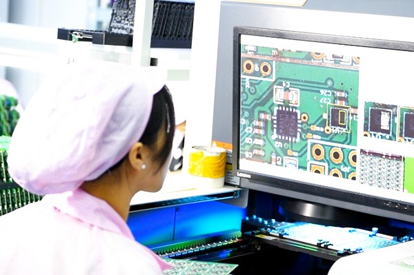
Step 2: Perform Initial Visual and Physical Inspection
Inspect the manufactured PCB for physical defects. Look for manufacturing inconsistencies like over-etching or under-etching of traces, which can alter impedance. Measure trace widths using a caliper or microscope if possible, and compare them to the design specs. Even a 10% deviation in trace width can lead to a noticeable impedance shift.
Step 3: Conduct TDR Testing
Use TDR to identify the location and severity of impedance discontinuities. Connect the TDR equipment to the trace under test and analyze the resulting waveform. Look for spikes or dips that indicate reflections. If a mismatch is detected at a specific point, such as a via or connector, note its location for further investigation.
Step 4: Use VNA for Frequency-Domain Analysis
For high-frequency designs, perform VNA testing for PCBto measure return loss and insertion loss. Analyze the data to confirm whether the impedance mismatch affects the signal across the operating frequency range. This step is crucial for applications where signals operate above 1 GHz, as small mismatches can cause significant performance degradation.
Step 5: Implement Fixes and Retest
Based on the test results, apply corrective measures. Common fixes include:
- Adjusting trace widths or spacing to match the target impedance.
- Adding proper termination resistors to reduce reflections.
- Revising the stack-up to ensure consistent dielectric properties.
- Improving via designs to minimize impedance discontinuities.
After making changes, retest the PCB using TDR or VNA to confirm that the issue is resolved. Repeat the process if necessary until signal integrity is restored.
Best Practices for Preventing PCB Signal Integrity Problems
While troubleshooting is essential, preventing PCB signal integrity problemsduring the design phase can save time and resources. Here are some proven strategies to maintain impedance control and ensure reliable performance:
- Controlled Impedance Design:Specify impedance requirements clearly in your design files and work with your manufacturer to achieve tight tolerances, typically within ±10% of the target value.
- Proper Stack-Up Planning:Design your layer stack-up to minimize variations in dielectric constant and ensure consistent impedance across layers.
- Simulation Tools:Use simulation software to model signal behavior and identify potential impedance issues before manufacturing.
- Ground Planes:Include continuous ground planes beneath signal traces to provide a stable return path and reduce EMI.
- Termination Techniques:Implement series or parallel termination to match impedance and prevent reflections.
By following these practices, you can reduce the likelihood of impedance mismatches and maintain signal integrity in your designs.
Challenges in Impedance Testing and How to Overcome Them
While impedance testing troubleshootingis a powerful approach, it comes with challenges. Understanding these obstacles and how to address them can improve your testing accuracy.
- Equipment Limitations:TDR and VNA equipment can be expensive and require calibration. Ensure proper calibration and use equipment suited for your frequency range (e.g., a VNA with a range up to 20 GHz for high-speed designs).
- Complex Geometries:Vias, connectors, and bends in traces can complicate measurements. Use de-embedding techniques during VNA testing to isolate specific sections of the circuit.
- Manufacturing Variations:Small deviations in material properties or etching can affect results. Work closely with your manufacturer to ensure consistency and request test coupons for impedance verification.
By anticipating these challenges, you can refine your testing process and achieve more reliable outcomes.
Conclusion: Mastering PCB Signal Integrity with Impedance Testing
Troubleshooting PCB signal integrity issuesdoesn't have to be a daunting task. By leveraging tools like TDR testing for PCBand VNA testing for PCB, you can accurately detect and resolve PCB impedance mismatchproblems. Whether you're dealing with signal reflections, crosstalk, or timing errors, a systematic approach to impedance testing troubleshootingcan restore performance and reliability to your designs.
Start with a solid design foundation, use the right testing tools, and apply best practices to prevent issues before they arise. With these strategies, you'll be well-equipped to tackle signal integrity challenges and ensure your PCBs meet the demands of high-speed applications.
Share · · · ·
The Role of Flux in PCB Wave Soldering: Selection, Application, and Residue Removal
March 16, 2026PCB wave soldering flux types include rosin, water-soluble, and no-clean options with varying activity levels for oxide removal and solder flow. This guide covers selection criteria, spray foam drop-jet application methods, residue removal processes, and alternatives like nitrogen blanketing to boost joint reliability and yields for engineers.
Article
Achieving Uniform Solder Fillets in PCB Wave Soldering: Process Control
March 16, 2026Achieve uniform solder fillets in PCB wave soldering with process control strategies. Optimize flux, preheat, wave height, conveyor speed for consistent fillet shape, height, and wetting balance. Includes visual inspection tips and troubleshooting for reliable through-hole assemblies. Boost quality in production.
Article
Optimizing Conveyor Speed for Efficient PCB Wave Soldering
March 16, 2026Learn PCB wave soldering conveyor speed calculation to manage dwell time, immersion depth, and throughput effectively. Electric engineers get practical steps, best practices, and troubleshooting tips for higher process efficiency and fewer defects in wave soldering operations.
Article
Understanding IPC Standards for PCB Surface Finishes: Ensuring Quality and Compliance
March 11, 2026Understand IPC standards IPC 4552 ENIG and IPC 4553 immersion silver for PCB surface finishes. Ensure compliance, enhance solderability, and prevent common defects to achieve reliable, high quality circuit boards.
Article
Miniaturization Challenges in PCB Assembly
March 11, 2026Navigate the complexities of high density interconnect PCB assembly and precise component placement. Learn to tackle miniaturization challenges, from tiny part handling to thermal stress, ensuring robust and reliable electronics.
Article
High Speed Routing Techniques: PCB
March 11, 2026Master high speed routing in PCBs to ensure signal integrity and minimize electromagnetic interference. Learn essential techniques for robust designs, from controlled impedance to differential pair strategies. Prevent performance issues and achieve reliable electronics.
ArticleGet Instant PCB
Quotations
Full-featured PCB
manufacturing service at low cost.